
Long Cycle Life Scalable Lithium Battery PowerModule-12.8V45Ah
Safe, reliable and maintenance-free Power On Demand
Overview
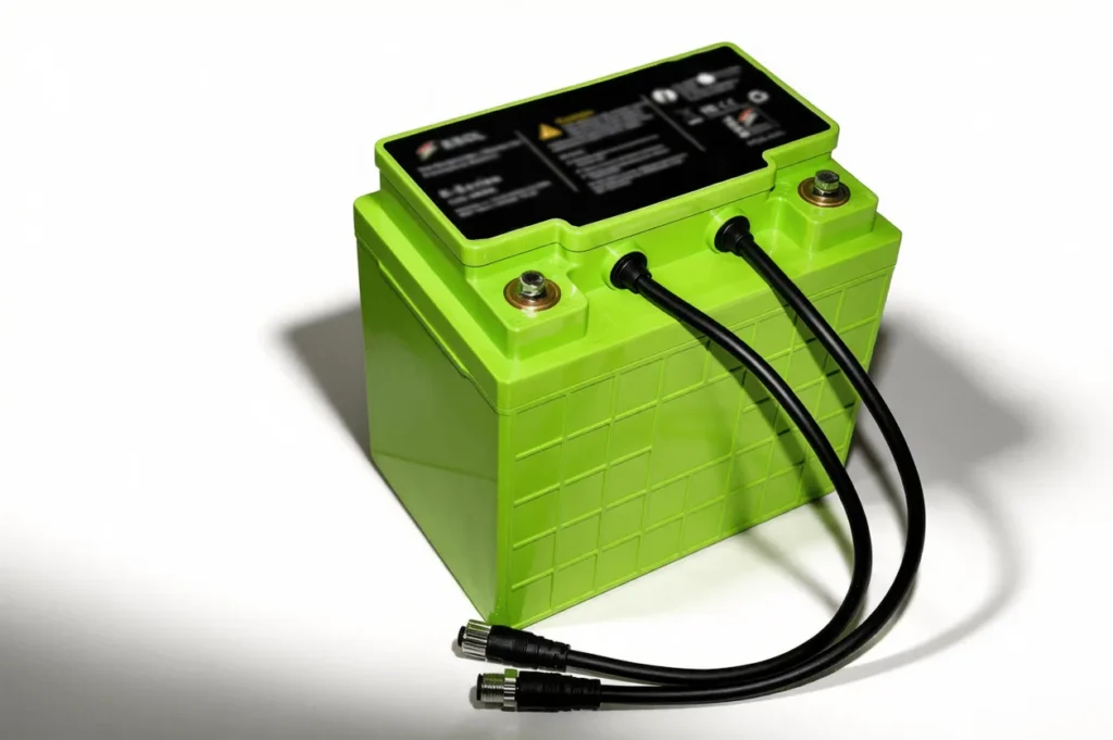
Scalable Lithium Battery 12.8V45Ah,This battery module can be connected together in series and parallel configurations to meet the voltage and power needs of the application. An external contactor or some other means of protection needs to be connected in series with this battery module to protect against over-charging and over-discharging the modules.
Features
- >4000 cycles at 80% DOD
- Create systems 12 – 1000 V
- Series and/or parallel operation
- Temperature monitoring of cells and terminals
- inter and intra balancing
- Rugged mechanical design
- Footprint of Group 1 lead acid case
- LED battery status indicator
- Communication of monitored data via Battery Management System(BMS)
- Module electronics monitors cell voltage, temperature, current, SOC, warning & alarm
- Flame retardant plastic
- FCC Class B, CE,UL1642(cell)
Technical Specification
| Feature | Comments |
| One Battery module | 45AHr or 576WH |
| Size | 197 mmx 131 mmx 183 mm |
| Weight | 6.5Kg |
| Terminals,Female-Threaded | M6x1.0 |
| Nominal module voltage | 12.8V |
| Maximum module voltage | 14.6V |
| Minimum module voltage | 10V |
| Nominal load current | 80A max. continuous current @ 23° C |
| Peak load current | 120A max for 30 sec @ 23° C |
| Recommended charging current | 40A (1C) |
| Charging Temperature | 0°C to 45°C |
| Discharging Temperature | -10°C to 50°C |
| Storage temperature | -40°C to 50°C |
| Operating humidity | 5% to 95%, non-condensing |
| Charge Disconnect | When the Battery modules are charged to full, they will communicate with BMU, and the BMU has the capability to turn off the charger or open the main contactor. The battery module itself does not have any switch to disconnect the charger. |
| Cell Balancing | The intra-module balancing circuitry is used to compensate slight capacity imbalance among the eight cell banks within a battery module. The inter-module balancing circuitry is used to compensate slight capacity imbalance between different battery modules in series connection. |
| State of Charge Measurement | Individual cell voltage and charge/discharge current will be used to monitor the state of charge (SOC) of the battery module. The estimated capacity used for the calculations will be adjusted to meet the capacity of the lowest capacity cell bank when the pack is fully cycled. The state of charge will be adjusted for normal self discharge of the pack when the unit is not on charge. |
| RS-485 Communication Uplink | RS-485 Communications will be used to communicate with the Battery Management Unit (BMU) or connection to other battery Modules. |
| RS-485 Communication Downlink | RS-485 Communication connection from Downstream battery module. |
| RS-485 insulation voltage rating | 1414V 5000V rms for 1 minute |
| Status LED | A Dual LED on module to indicate working status. One is green and the other one is red. Blinking of the green LED indicates that the module is working properly. Blinking of the red LED indicates that the module has failure and needs service. |